

Marine Fouling: Challenges and Impacts
Marine fouling (biofouling) is the accumulation of aquatic organisms on submerged surfaces – everything from bacterial slime and algae to barnacles, mussels, and other marine life attaching to hulls, offshore structures, and intake pipes. This growth occurs rapidly and can have serious impacts on marine assets. Heavy fouling increases a ship’s weight and hydrodynamic drag, which forces engines to work harder. Studies have found that fouling can boost a vessel’s fuel consumption by as much as 40%, translating to billions of dollars in extra fuel cost industry-wide. On a global scale, hull fouling is estimated to account for about 9% of the entire shipping fleet’s fuel consumption, adding roughly 80 million tons of excess CO2 emissions and $16 billion in fuel costs per year.
Fouling doesn’t just affect ship hulls – it also clogs seawater cooling systems and offshore equipment. Marine growth inside cooling water intakes and piping can constrict flow and foul heat exchangers, leading to reduced cooling efficiency or even engine overheating and failure. On offshore oil platforms, thick barnacle and mussel growth on underwater members adds weight and increases hydrodynamic loading, stressing the structure during waves and storms. In short, unchecked marine growth can raise operating costs, increase downtime for cleaning and repairs, and shorten the service life of assets through corrosion acceleration and material damage. These problems make effective antifouling measures a critical aspect of marine asset management.
Overview of Antifouling Strategies

Over the years, the marine industry has developed several strategies to prevent or reduce biofouling on ships and structures. Traditional approaches include antifouling coatings (specialized hull paints) formulated with biocides like copper compounds that slowly leach out and deter organism growth. Older tin-based paints (tributyltin, or TBT) were extremely effective but were globally banned in 2008 due to their toxicity to marine life. Modern antifouling paints typically use copper oxide and other biocides or slick non-stick (foul-release) coatings to impede growth. Regular hull cleaning by divers or hull-cleaning robots is another method to remove fouling before it becomes severe. Other physical techniques such as ultrasonic antifouling (using ultrasonic transducers on the hull) and UV light emitters in sea chests have emerged to continuously discourage biofouling without chemicals.
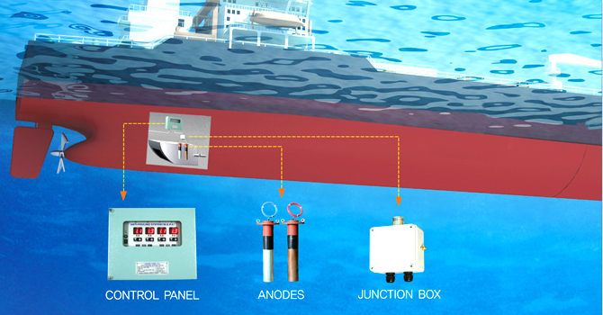
Marine Growth Prevention Systems (MGPS) – sometimes called Impressed Current Anti-Fouling (ICAF) systems – are an active antifouling strategy that uses sacrificial anodes or impressed currents to release ions (like copper) or chlorine into seawater. This ion release creates an environment where barnacles, mussels, and algae cannot settle or survive. For example, MGPS commonly employ copper anodes mounted in a ship’s sea chest or cooling pipelines; as a small current is passed, the anodes release minute concentrations of copper (on the order of 2 parts per billion) which effectively prevents larvae from attaching. These systems protect internal piping without the use of chemical dosing, and are widely used on ships and offshore installations to keep critical cooling water circuits clear of growth.
While coatings and cleaning address fouling on external surfaces, cathodic protection systems – the focus of this article – offer a way to combat fouling and corrosion using electrochemistry. Cathodic protection is traditionally used to prevent corrosion of metal surfaces by making the structure a cathode in an electrochemical cell. Interestingly, cathodic protection (especially impressed current systems) can also incidentally help inhibit biofouling in some cases, or at least work in tandem with antifouling measures. Below, we explore the two main types of cathodic protection that use anodes – sacrificial anodes and impressed current systems (ICCP) – and how they contribute to both corrosion prevention and marine growth control.
Sacrificial Anode Cathodic Protection (SACP)
Sacrificial anode systems, also known as galvanic cathodic protection, rely on highly active metal anodes that corrode (sacrifice themselves) to protect the more valuable steel structure. The anodes – typically made of zinc, aluminum, or magnesium alloys – are bolted or welded to the hull or structure and electrically connected to it. Because these metals are more anodic (less noble) than steel in the galvanic series, they preferentially oxidize in seawater, releasing electrons that flow to the steel and cathodically polarize it (making the steel surface the cathode). In essence, the sacrificial anodes “take on” the corrosion, sparing the structure. The steady dissolution of the anodes provides a continuous protective current that prevents the steel from rusting.
Sacrificial anode CP systems are passive and simple – they require no external power or complex controls. This makes them very reliable; as long as the anode material remains, protection is delivered automatically. Sacrificial anodes also help mitigate biofouling to a minor extent: the protective current causes the steel surface to develop alkalinity and calcareous coatings (Calcium/Magnesium salts) that can make it slightly harder for organisms to adhere. However, on their own, sacrificial anodes are not a primary antifouling solution – in practice they are combined with antifouling coatings for hull fouling control.
Galvanic anodes are widely used in marine environments due to their ease of installation and proven performance. They are common on smaller vessels, harbor facilities, and offshore structures. For example, a typical fixed offshore platform will have dozens or even hundreds of aluminum alloy anodes welded along its underwater jacket to provide corrosion protection for 20+ years. Each anode can be quite large – often 100–200+ kg for deepwater applications – reflecting the amount of material needed to last for the structure’s design life. Sacrificial anodes are also spaced along subsea pipelines (usually as “bracelet” anodes clamped around the pipe at intervals) to protect the pipeline’s length. A spacing of roughly one anode every few hundred meters is common, though optimal spacing is determined by detailed engineering based on seawater resistivity and pipeline coating quality.
The main advantages of sacrificial anode systems are their simplicity and independence from external power. They can be installed on virtually any structure and will begin protecting as soon as immersed in electrolyte. There is minimal risk of system failure since no moving parts or power systems are involved. However, this method has some drawbacks: the amount of protective current is limited by the anode material and area, so very large structures need many anodes. They also add weight and drag (in the case of hull-mounted anodes on ships) and must be periodically replaced once consumed. According to corrosion experts, galvanic anode systems tend to have a shorter lifespan and limited capacity, and they cannot easily be adjusted or turned off – the protection level is not easily controllable once installed. Despite these limitations, sacrificial anodes remain a backbone of corrosion protection for countless marine assets due to their reliability and ease of use.
Impressed Current Cathodic Protection (ICCP)
Impressed Current Cathodic Protection (ICCP) systems take a more active approach. Instead of relying on the natural galvanic potential of sacrificial metals, ICCP uses an external DC power source (rectifier) to drive protective current to the structure. In an ICCP setup, inert anodes made from materials like titanium coated with mixed metal oxides (MMO) or platinum are mounted on the structure’s hull or submerged near it. These anodes are connected to the positive terminal of the DC power supply, and the structure is connected to the negative terminal, making the structure the cathode. When energized, the anodes discharge a controlled current into the seawater, which then flows onto the surface of the protected structure, polarizing it to a cathodic (negative) potential and halting its corrosion. The inert anodes themselves do not significantly corrode (they are designed to resist consumption, only releasing electrons and causing electrochemical reactions in the water such as oxygen reduction on the cathode). This means they can provide protection without needing regular replacement of anode material.
A hallmark of ICCP systems is their automatic control capability. They typically include reference electrodes mounted on the hull which measure the electrochemical potential of the hull with respect to seawater. A control panel uses this feedback to adjust the output current from the anodes, ensuring the hull’s potential stays in the desired range (usually around –0.8 V to –0.85 V Ag/AgCl for steel in seawater, which is sufficient to prevent corrosion). This closed-loop control prevents under-protection (if the potential rises too high, more current is applied) as well as over-protection (if the potential is too low/negative, current is reduced to avoid issues like coating damage or hydrogen evolution). The result is a consistent level of corrosion prevention optimized to conditions.
ICCP is often favored for large ships and structures because it can deliver high protection currents without the weight or hydrodynamic penalties of numerous sacrificial anodes. A few flush-mounted ICCP anode assemblies can replace dozens of bulky zinc anodes on a ship’s hull. Since the anodes are inert and only a small amount of material erodes over time, ICCP systems can operate for long periods (5–15+ years) before anode replacement, just requiring routine electrical maintenance. Impressed current systems thus offer high capacity and long-term efficiency – they can be sized to protect virtually any structure, large or small, by adjusting the power supply. As a reference, experts note that ICCP provides optimal corrosion protection with an adjustable output and generally enjoys a longer lifespan and higher current capacity compared to sacrificial anodes.
There are some trade-offs to ICCP. The systems are more complex and require a reliable power source (usually from the ship or platform’s electrical system). Installation involves mounting anodes, reference cells, and running cables and hull penetrations for the wiring, as well as installing the rectifier/control unit – this is a more involved process than simply welding on a sacrificial anode. The initial cost of ICCP equipment is higher, and specialist knowledge is needed to design and maintain the system. If the system fails or loses power, corrosion can progress rapidly (though often a safety factor of small sacrificial anodes or backup battery is provided on critical structures). Moreover, impressed current anodes driving high currents can cause unintended side effects such as producing chlorine gas (from seawater electrolysis) or interfering with nearby structures via stray currents if not properly designed. Despite these considerations, ICCP is a proven technology widely employed on ships and offshore units for robust corrosion protection. It effectively separates the antifouling function from the corrosion protection function: a ship with ICCP still uses antifouling paint or MGPS for biofouling, while ICCP handles corrosion prevention in an efficient manner.
ICCP vs. Sacrificial Anodes: Comparative Analysis
Both sacrificial anode systems and impressed current systems achieve the same fundamental goal – protecting structures from corrosion by making them cathodic – but they differ in implementation, cost, and practicality. Table 1 below summarizes the key differences between the two approaches:
| Criteria | Sacrificial Anode CP (Galvanic) | Impressed Current CP (ICCP) |
|---|---|---|
| Power source | No external power needed; driven by natural galvanic potential of anode metals. | Requires external DC power/rectifier to drive current. |
| Anode material | Consuming metal‑alloy anodes (Zn, Al, Mg) that corrode over time. | Inert anodes (e.g., MMO‑coated titanium) that emit current but are minimally consumed. |
| Control of output | Fixed output based on galvanic driving voltage; not easily adjustable or switchable. | Output is adjustable via a control unit; automatically regulated with reference electrodes to maintain optimal protection. |
| Maintenance | Periodic replacement of anodes when consumed (typically during dry‑dock or scheduled maintenance). | Periodic monitoring/calibration of electrical system; anodes last 5 – 15 + years, but electronics need upkeep. |
| Installation | Simple installation (weld or bolt anodes to structure); minimal technical complexity. | More complex: mount anodes, reference cells, cabling, hull penetrations, power unit; requires skilled design. |
| Initial cost | Lower (anodes are inexpensive; little infrastructure needed). | Higher (equipment and power system installation). |
| Operating cost | No ongoing power cost, but anode replacement and added vessel drag increase long‑term cost. | Small electrical power cost; less‑frequent anode replacement. Monitoring adds some cost, but often lower long‑term cost for large structures. |
| Protection capacity | Limited by size/number of anodes and water chemistry; very large structures require many anodes. | Scalable to any size by increasing current; high output capacity—large hulls or complex structures need only a few anodes. |
| Effect on fouling | Can form calcareous deposits that passively discourage some fouling, but not a primary antifouling method; usually paired with coatings. | Anode currents can generate chlorine locally, slightly reducing biogrowth near anodes; often paired with coatings or dedicated MGPS for fouling control. |
As highlighted above, sacrificial anode systems excel in simplicity – they are economical and straightforward to install, with no risk of power loss, which makes them very attractive for smaller or remotely located assets. However, they have inherent limitations in longevity and power: once the anode material is consumed, protection ceases, so they must be designed with enough mass to last until the next service interval. In contrast, ICCP systems offer greater control and endurance, delivering protection through an adjustable current that can be tuned to environmental conditions. This is especially valuable for larger vessels or platforms where corrosion rates may vary over time. Industry guidelines note that sacrificial anodes are valued for being fail-safe and easy, but come with shorter life and limited capacity, whereas ICCP provides optimum protection with a long service life (at the cost of complexity and higher upfront expense). In practice, the choice between ICCP and sacrificial anodes depends on the specific application, size of the structure, available power, maintenance strategy, and regulatory considerations. Often a combination is used – for example, a ship may have an ICCP system for the hull and also a few sacrificial anodes on rudders or propellers, plus an MGPS for internal pipes.
Applications Across Marine Assets
Effective antifouling and cathodic protection are employed across a wide range of marine industries, each with its own specific needs:
Ships and Vessels
Ships of all types must contend with both hull biofouling and hull corrosion. The typical solution is a multi-pronged approach: the hull is coated with antifouling paint to minimize organism growth, and a cathodic protection system prevents electrochemical corrosion of the hull steel. Many large commercial ships (tankers, container ships, cruise ships, etc.) and naval vessels use ICCP systems for hull corrosion protection. ICCP anodes and reference electrodes are installed flush with the hull, usually on the bottom and stern areas, to protect the wetted surface and appendages. This reduces the need for numerous sacrificial anodes, saving fuel by avoiding extra drag. Smaller ships and boats, on the other hand, often rely on sacrificial anodes – you’ll see zinc anode bars or discs on the hull, rudder, and propulsion gear of many yachts, fishing boats, and tugs. These anodes are simple and work well for modest-sized vessels or where power for ICCP is not available.
In addition to external hull protection, ships must also prevent marine growth in their internal seawater systems. Sea chest grids, pipework, heat exchangers, and fire pumps that use seawater are prone to biofouling. To address this, many vessels employ Marine Growth Prevention Systems (MGPS/ICAF) that use anodes to dose small amounts of copper and chloride ions into the seawater flow. This practice is widespread – Cathelco (Evac), a major MGPS provider, notes that their impressed-current antifouling systems are installed on over 50,000 vessels worldwide to stop mussels and barnacles from blocking ship cooling pipes. By keeping internal systems clear, MGPS helps maintain engine cooling efficiency and prevents the kind of dangerous fouling-related breakdowns mentioned earlier. The combined use of antifouling coatings, ICCP for corrosion, and MGPS for internal antifouling allows ships to operate efficiently between drydock intervals with minimal performance loss due to biofouling.
Offshore Platforms and Energy Facilities
Offshore oil & gas platforms, wind farm monopiles, and other fixed marine structures face harsh conditions for both corrosion and fouling. Sacrificial anode CP is extremely common on offshore steel jackets – large aluminum alloy anodes are welded at intervals on legs, cross-bracings, and subsea equipment. These anodes are designed to provide corrosion protection for the intended life of the platform (often 20–30 years) without replacement. For example, a North Sea jacket platform might be outfitted with hundreds of kilogram-size anodes distributed over the structure to ensure complete cathodic coverage. Thick biofouling inevitably grows on platform legs and risers; while sacrificial anodes do not prevent this growth, they continue to protect the steel under the fouling. Operators will periodically have divers scrape off heavy growth if it becomes problematic, but generally the fouling is tolerated unless it affects safety or inspections.
Newer offshore facilities sometimes opt for ICCP systems instead or in addition to galvanic anodes. ICCP can be advantageous on very large floating structures like FPSOs (Floating Production Storage and Offloading vessels) or semi-submersibles, which have onboard power and can benefit from reduced anode weight. Retrofitting ICCP is also a solution if an existing platform’s sacrificial anodes deplete before end-of-life – anodes and reference cells can be installed via divers or ROVs and tied to a power source topside to restore protection. Offshore wind turbines, which have electrical generators, have started using ICCP on their monopile foundations to avoid the need for massive aluminum anodes and to facilitate remote monitoring of corrosion protection from shore. Regardless of CP method, offshore installations must also consider antifouling to protect critical components. Sea-water intake systems on platforms (for firewater or cooling) often use MGPS anodes or electrochlorination to prevent blockage. Some subsea equipment may be fitted with antifouling coatings or even UV lights on intakes to mitigate growth. Thus, a combination of sacrificial anodes/ICCP for corrosion and targeted antifouling measures for key areas is common in the offshore sector.
Subsea Pipelines and Cables
Subsea pipelines (and to some extent power/fiber-optic cables with metallic armor) are protected primarily by sacrificial anode cathodic protection. Pipeline sections are outfitted with bracelet anodes at regular spacing along their length. These anodes, usually aluminum alloy, are clamped or bolted onto the pipe over its coating. They are designed based on pipeline length, diameter, coating quality, and environmental factors so that their combined output will keep the entire pipeline polarized in the safe range. A rule of thumb in earlier decades was an anode every ~400 meters for well-coated lines, but actual spacing is optimized through CP modeling. The anodes corrode slowly and continuously, protecting the pipe from generalized corrosion and pitting, even if the external coating sustains damage or holidays. For long pipelines, sacrificial CP is favored because it is autonomous and maintenance-free — running power cables or remote ICCP anodes along a 100-km subsea pipeline is impractical. Near platforms or shore crossings, sometimes impressed current ground beds or anodes are used to supplement protection (for instance, anodes at a platform jacket can also protect tie-in spools or pipeline end manifolds via the electrical continuity). Overall, subsea pipelines demonstrate the reliability of sacrificial anodes: many pipelines installed decades ago with galvanic CP continue to operate safely with their original anodes still slowly wasting away, having prevented corrosion all that time.
It’s worth noting that biofouling on subsea pipelines is usually less of a direct operational concern (since a bit of marine growth on the pipe doesn’t significantly affect its function). However, biofouling can increase the effective diameter and roughness of pipeline bundles or umbilicals, potentially affecting hydrodynamic stability on the seafloor, and can make inspections (via ROV sonar or cameras) more challenging. As a result, some pipeline operators apply antifouling coatings or periodic cleaning for critical shallow-water lines, but in most cases the natural growth is left unless it interferes with something. The main emphasis for pipelines remains on corrosion control via CP, with fouling control being secondary except in specific scenarios.
Cooling Water Systems and Sea Chests
Marine and coastal facilities that use seawater for cooling – including power plants, desalination plants, coastal industrial facilities, and ships’ engine cooling systems – must prevent biofouling in their intake tunnels, piping, and heat exchangers. Even a thin layer of slime or shell growth in a heat exchanger can drastically reduce heat transfer efficiency, and unchecked mussel growth can clog pipes completely. Marine Growth Prevention Systems (MGPS) are widely used in these applications. A common arrangement is to install pairs of antifouling anodes (usually copper and aluminum) in the sea chest or pump suction of the cooling circuit. When energized, the copper anode releases a controlled dose of copper ions, and the aluminum anode produces aluminum hydroxide – this combination spreads through the pipework and prevents organisms from settling and multiplying. The concentration of copper ion is very low (on the order of 2 ppb as mentioned), but it is enough to create an environment that is biocidal to barnacles and mussel larvae. The aluminum hydroxide helps by flocculating the released copper, distributing it and also forming a thin protective film on pipes.
Such impressed current antifouling systems (MGPS/ICAF) are essentially a specialized use of sacrificial anodes for biofouling control rather than corrosion control. In fact, they often serve dual-purpose: the slight anodic current and metal ions also give a bit of corrosion inhibition to the piping system. These systems are prevalent on ships (for engine cooling, firefighting systems, condensers) and are also used in onshore power plants and jetties. An alternative approach is electrochlorination, where inert anodes (like MMO-coated electrodes) generate sodium hypochlorite by splitting seawater salt – this chlorinated water is then dosed into the cooling system to kill growth. Both copper-ion and electrochlorination methods achieve similar results; the choice depends on the specific organism risks and regulatory constraints. Real-world examples include: coastal power stations with electrochlorination plants at their intakes to continuously produce chlorine for biofouling control, and large ships that have cupro-nickel heat exchanger tubes protected by a combination of small zinc anodes for corrosion and MGPS for biofouling. In all cases, maintaining flow and heat transfer by preventing marine growth is vital, and anode-based antifouling systems have proven to be an efficient, low-maintenance solution.
Installation and Maintenance Best Practices
Implementing cathodic protection and antifouling systems on marine assets requires adherence to best practices in both installation and upkeep. Below are some key guidelines to ensure these systems perform effectively over their service life:
-
Thorough Design and Positioning: Properly engineer the CP system for complete coverage. Calculate anode requirements (size, number, placement) so that all parts of the structure receive protection current. For ICCP, position anodes and reference cells in locations that will protect the entire wetted surface (e.g. near the stern, bow, and midsections of a hull) and not be blocked by geometry. For antifouling anodes in cooling systems, install them as close to the water intake as possible so ions disperse through all downstream piping.
-
Secure Installation: Ensure sacrificial anodes are firmly attached with good electrical contact to the structure (welded pads or bolted connections on clean, unpainted metal). Poor contacts can negate protection. ICCP anodes must be mounted and sealed correctly to prevent leaks through hull penetrations, and cables should be well insulated and clamped to avoid damage. All connections should be checked for continuity – the protected structure must be electrically continuous (bonded) so that anodes protect every part of it.
-
Regular Inspection and Cleaning: Include CP and antifouling devices in routine maintenance inspections. Divers or ROVs should visually check hull anodes on ships and platforms for consumption levels and damage. Sacrificial anodes generally should be replaced when they are about 50% or more consumed to maintain safety margin. ICCP anodes and reference electrodes should be cleaned of any marine growth or calcareous buildup that could insulate them (a light calcareous coating is normal, but excessive deposits or biofouling on ICCP anodes can reduce current output). For MGPS, inspect the anodes at least during scheduled drydocks – copper anodes may erode or get covered in scale and will need occasional cleaning or replacement as per the manufacturer’s guidance.
-
Monitoring and Record-Keeping: Track the performance of cathodic protection using measurements. For sacrificial systems, periodically perform potential surveys (using a reference electrode in water and a voltmeter) at various points on the structure to ensure the protective potential is being maintained (typically -0.8 V or more negative vs Ag/AgCl for steel). Impressed current systems usually have built-in monitoring – operators should log the hull potential readings and anode output currents regularly. Any drift in potentials or high outputs can indicate coating damage or anode deterioration, prompting corrective action. Many modern ICCP systems can be monitored remotely and even adjusted via control software; leveraging these features (or newer IoT-based remote CP monitoring sensors) can greatly improve maintenance efficiency.
-
Timely Replacement and Adjustments: Plan to replace sacrificial anodes during routine drydocks or underwater maintenance windows before they are fully consumed. It’s prudent to carry some spare anodes for critical areas that might deplete faster (e.g. near splash zones or hot spots). For ICCP, calibrate the reference electrodes periodically (some systems allow checking them against a portable reference cell) and replace any that are faulty. If an ICCP system shows consistently high output (meaning it’s working hard to protect, possibly due to coating deterioration), consider cleaning the hull or touch-up painting to reduce the load on the CP system. Always follow the manufacturer’s guidelines for servicing ICCP power units – cooling fans, electrical connections, etc., should be kept in good order to prevent outages.
-
Compliance with Standards: Adhere to relevant standards and regulations during installation and maintenance. Classification societies (ABS, DNV, Lloyd’s, etc.) and organizations like NACE/AMPP provide criteria for cathodic protection system design on ships and offshore structures. Ensure that the CP system is commissioned properly – for example, a polarization survey after installing ICCP to verify that the full structure is within protection potential. Similarly, MGPS installations should comply with safety standards (since they involve electrical equipment in water) and dosage regulations (not exceeding allowed biocide release levels).
By following these best practices, asset owners can achieve reliable long-term performance from both sacrificial and impressed current systems, minimizing surprises such as unexpected anode depletion, system failures, or insufficient protection. Proactive maintenance not only preserves the structure but also can save costs – for instance, keeping an ICCP system well-tuned may reduce overall fuel or power usage by avoiding over-protection, and maintaining antifouling systems prevents efficiency losses in heat exchangers and hull performance.
Environmental Considerations and Regulations
Because antifouling and cathodic protection technologies interact with the marine environment (through chemical releases or electromagnetic effects), they are subject to environmental regulations and must be managed to avoid ecological harm. A historical example is the ban on toxic TBT antifouling paints – the International Maritime Organization (IMO) adopted a treaty prohibiting tributyltin coatings effective 2008 after it was shown to cause severe harm to marine organisms and food chains. This ban propelled the development of less harmful antifouling solutions, including low-toxicity paints and non-biocide alternatives.
Modern antifouling systems like MGPS that use copper or chlorine are also regulated to ensure they do not pollute the water. In the European Union, the use of active substances for antifouling falls under the Biocidal Products Regulation (EU BPR). Copper anode systems are permitted, but the copper ion dosage must be kept within safe limits (a few parts per billion). In fact, manufacturers ensure their systems meet these requirements – for example, Evac’s Cathelco MGPS operates at around 2 ppb copper, in compliance with EU biocide directives. This concentration is enough to prevent fouling but too low to significantly impact non-fouling marine life beyond the immediate vicinity. Likewise, any chlorine produced by antifouling anodes dissipates quickly; however, operators must be mindful of local rules on chlorine discharge (for instance, power plants often have limits on residual chlorine in cooling water outflow).
For sacrificial anodes, the environmental consideration is the release of metal ions (zinc, aluminum, etc.) into the water as the anodes corrode. Zinc anodes historically contained a small percentage of cadmium (as an activator), which is a toxic heavy metal. Recognizing this, regulators have pushed for cleaner anode compositions. In U.S. waters, the EPA’s Vessel General Permit (VGP) guidelines (2013) advise vessel operators to use less toxic anode materials when possible – specifically recommending aluminum anodes in saltwater (and magnesium in freshwater) instead of traditional zinc, to reduce the introduction of cadmium and excess zinc into the ocean. After 2013, new ship builds and dry-dock refits have largely shifted to aluminum-based anodes for seawater use, which contain no cadmium and have a more benign environmental footprint. Aluminum anodes also tend to form an inert aluminum oxide surface film as they corrode, which can limit the bioavailability of aluminum in the water. Overall, while sacrificial anodes do release metals, studies and field experience have generally shown the environmental impact to be localized and low – especially compared to the unmitigated corrosion they prevent (which would release large quantities of rust and heavy metals if the structure were allowed to corrode).
Another environmental and regulatory aspect is the prevention of invasive aquatic species transport via biofouling. When ships with heavy hull fouling travel between ports, they can carry barnacles, mollusks, or algae to new ecosystems, potentially becoming invasive species. This has become such a concern that the IMO issued guidelines for biofouling management, and countries like New Zealand and Australia have regulations requiring vessels to arrive with a clean hull or risk penalties/quarantine. Effective antifouling, therefore, not only improves performance but protects biodiversity. Governments and international bodies are increasingly encouraging technologies that minimize chemical use while preventing biofouling to address this issue.
In summary, compliance with environmental regulations is now an integral part of using antifouling and cathodic protection systems. Operators must choose antifouling coatings and anode systems that are approved for use (with regard to biocidal ingredients), and they must monitor and record any discharges (like copper or chlorine levels) as required by law. The trend is toward greener solutions – for instance, port authorities and navies are investigating foul-release coatings (which have no biocides) and robotic hull cleaning to eventually reduce reliance on any biocidal release. In the CP realm, the move from zinc to aluminum anodes, and the use of ICCP (which theoretically releases less metal overall by using power instead of sacrificial mass), are steps aligned with environmental stewardship.
Future Trends and Innovations
Looking ahead, marine antifouling and cathodic protection technologies are evolving to become more efficient, environmentally friendly, and smart. Several notable trends and innovations are on the horizon:
-
Eco-Friendly Antifouling Methods: With growing regulatory pressure to reduce biocide use, there is significant interest in non-toxic antifouling solutions. Futuristic approaches include ultra-smooth foul-release coatings (e.g. silicone or fluoropolymer based paints that prevent organisms from sticking strongly, so they wash off when the vessel is in motion) and biomimetic surfaces that mimic shark skin or other natural antifouling surfaces. Underwater robotic cleaners are also being developed to routinely groom hulls and keep them clean without drydocking. In some sectors, keeping vessels out of water when not in use (“dry docking” small craft or using floating docks for idle periods) is being adopted to avoid fouling buildup. For niche applications like niche areas and sea chests, built-in ultraviolet (UV) lighting systems have shown promise in sterilizing incoming water and preventing larvae settlement, and ultrasonic transducers mounted on hulls can create ultrasonic vibrations that deter algae growth. These methods produce no chemical pollution, aligning with future environmental goals. According to industry analyses, the future of antifouling will likely be a mix of such technologies – e.g. periodic robot cleaning plus low-friction coatings – to achieve zero harmful biocide release.
-
Advancements in Cathodic Protection: While cathodic protection is a mature field, innovations are occurring in materials and monitoring. Improved anode alloys are continually being developed – for instance, aluminum-zinc-indium alloys have largely replaced older zinc anodes, offering higher efficiency and no toxic elements. Research is ongoing into self-healing coatings that work in tandem with CP, where the coating releases corrosion inhibitors if damaged, reducing CP demand. On the ICCP front, modern systems are incorporating digital control and remote monitoring capabilities. Impressed current systems can now be tuned via software, and data on hull potential, anode current, etc., can be sent to maintenance teams onshore in real time. This allows for predictive maintenance – if an anode is deteriorating or a coating has been damaged (requiring more current), the change is spotted early and can be addressed. The use of IoT sensors on pipelines and offshore structures to monitor CP status is growing, which will likely become a standard part of integrity management. Future ICCP designs might also integrate with overall asset management systems, adjusting protection levels based on operational context (for example, reducing current output when a ship is in port and fouling risk is higher, to avoid chlorine production that could harm marine life in enclosed harbors, then ramping up at sea).
-
Hybrid and Integrated Systems: We can expect to see more integration between antifouling and anti-corrosion systems. One example is combining ICCP with antifouling anodes in a unified system – some companies already offer control panels that handle both hull ICCP and MGPS from one unit, optimizing the overall current distribution. Another concept being explored is using CP current in novel ways for antifouling: for instance, applying an intermittent current or specific potential profile on a surface to discourage biofilm formation (a kind of “electrochemical antifouling” approach). While still in R&D, this could one day complement traditional methods.
-
Stricter Environmental Regulations Driving Innovation: As regulations tighten, especially on biocides, the industry is pushed to innovate. Some regulators have proposed phasing out all biocidal antifouling paints in the future, which would require a complete shift to solutions like UV, ultrasound, or ultra-smooth coatings. This is spurring research into next-generation coatings that use nanotechnology or surface microtexturing to physically resist fouling growth without leaching chemicals. The drive for sustainability is also evident in sacrificial anode usage – there is interest in anode recycling (recovering metal from spent anodes) and reducing anode mass by utilizing ICCP where feasible.
Overall, the future of marine growth prevention and cathodic protection will likely be characterized by smarter systems that are both kinder to the environment and more efficient in protecting assets. Ships and offshore structures could have “intelligent hulls” that actively monitor and protect themselves against both corrosion and fouling, with minimal human intervention. While the fundamental challenges of marine fouling and corrosion will always be present, ongoing innovation aims to control these issues in a way that maintains performance, reduces costs, and meets the increasing environmental expectations of the maritime industry.
Conclusion
Marine fouling and corrosion are twin enemies of any structure in the ocean, but through a combination of antifouling measures and cathodic protection, we have the tools to combat them. Sacrificial anode systems and ICCP systems each play a pivotal role in protecting assets – from the smallest boat to the largest offshore platform – extending their service life and ensuring safe, efficient operations. Sacrificial anodes offer simplicity and proven reliability, while impressed current systems provide power and precision; used together with modern antifouling techniques (coatings, MGPS, etc.), they form a comprehensive defense against the harsh marine environment. The choice of system must be tailored to the asset and its operational profile, taking into account regulatory requirements and environmental responsibility. By understanding the strengths of each approach and following best practices in design and maintenance, operators can significantly mitigate biofouling buildup and corrosion damage.
In essence, marine growth prevention using anode-based systems represents a marriage of biology and electrochemistry: it leverages advanced materials and electrical control to keep nature’s growth at bay and preserve man-made structures. As the industry moves forward, continuous improvement in these technologies – making them greener, smarter, and more robust – will ensure that ships sail smoother, platforms stand stronger, and pipelines flow longer, all while coexisting more harmoniously with the marine ecosystem.